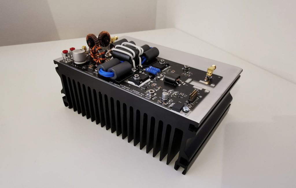
For optimal performance, the heatsink should have a thermal resistance of 0.1C/W or better at full fan speed. For the prototype I used ABL Components 180AB1500B, it is available in many countries from RS Components.
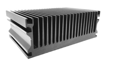
However, the thin anodised black layer had to be removed for better thermal contact transfer (although it improves heat transfer to air). To achieve 0.1C/W it needs some airflow, 2x 92mm 2500rpm fans should be enough for most situations, depending on duty cycle and environmental temperature. One of the important advantages is it has a thick, massive base with a large thermal capacity, which allows it to absorb a lot of thermal energy before getting hot, making best use of RX/TX cycles.
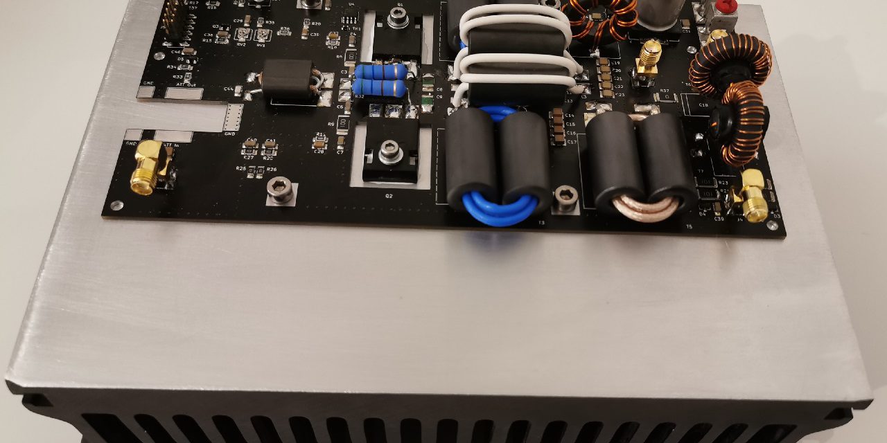
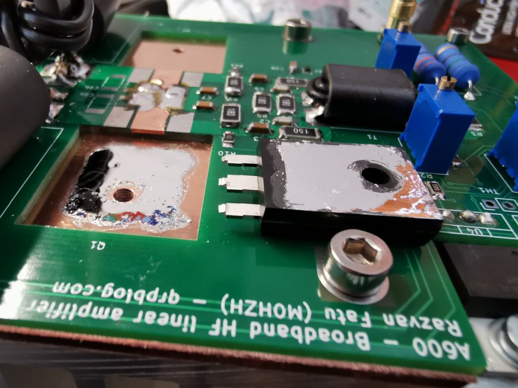
Special attention needs to be paid to mounting the transistors on the heatsink: they should be installed on a flat, clean and preferably polished (closer to the “mirror” look) area, with quality thermal paste and good even pressure.One of the best TIM is Gelid Solutions GC-Extreme, but it’s a bit tricky to spread evenly and is not designed to conduct electricty (which would be desirable, as the heatsink is the circuit ground).
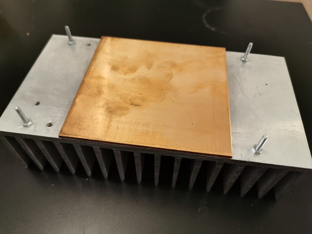
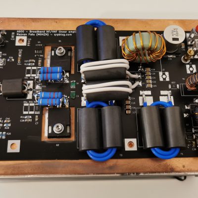
An alternative cooling system I have successfully tested on the previous prototype used a copper heat spreader between the transistors and the aluminum heatsink. This has multiple benefits, as it allows to use liquid metal thermal interface material (which corrodes aluminum) for the transistors mounting and also spreads the heat quicker thoughout the whole heatsink.
This means a lighter heatsink with a thinner base can be used, but in turn creates other challenges as copper is harder to machine. This is best for either high duty-cycle work (with a large heatsink) or a very compact, lightweight design that relies on high speed fans to quickly remove heat.


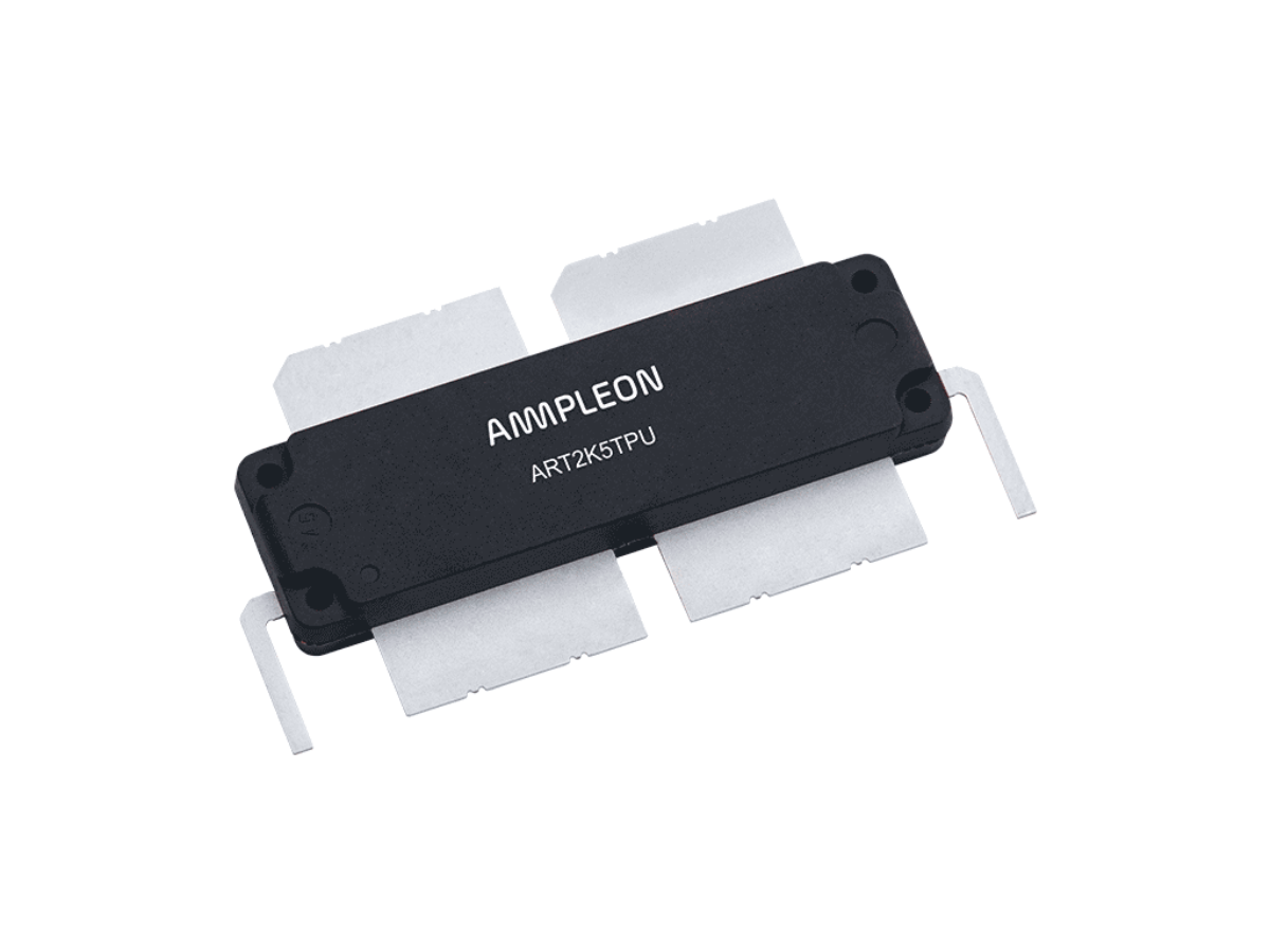
We build HF mplifier use BLF188XR and thermal pase using Coollabaratuary liquid pro but its dry about 3 mount and we worried het dissipation, Liquid pro advise nickel plated copper, I think must solder copper