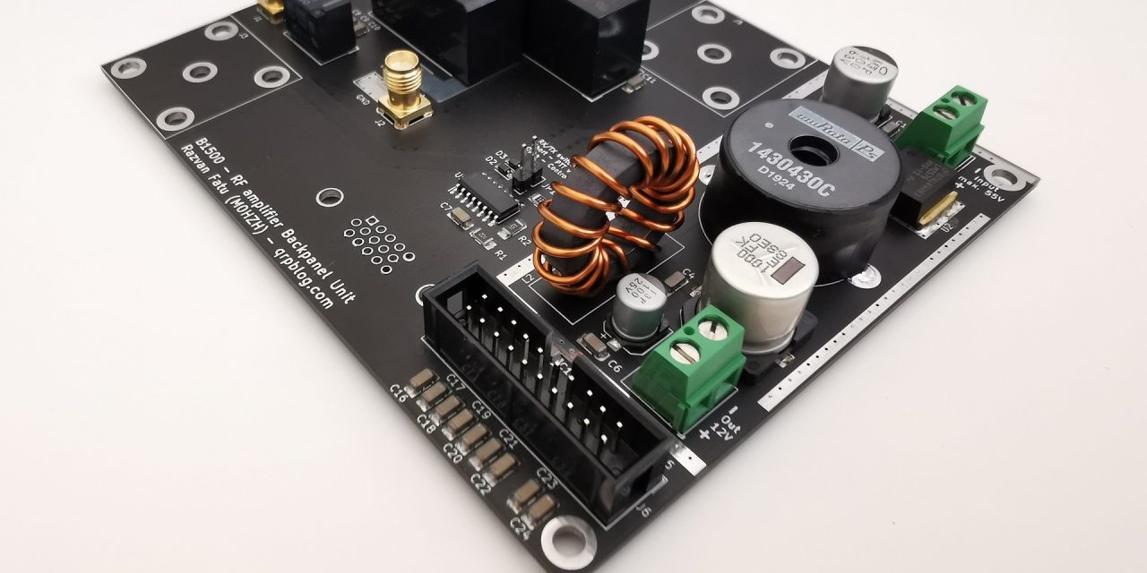
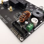
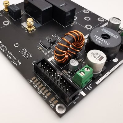
The B1500 RF amplifier Backpanel Unit is designed to sit between a LDMOS RF amplifier and the rest of your shack. It handles RX/TX switching, antenna selection and transceiver interfacing. It also has a clean, high-efficiency DC-DC converter that supplies 12V at a maximum of 3A for all the amplifier’s additional circuitry, display, relays and fans. It will run on any voltage from 15V to 55V.
Schematic and functionality
For the schematic and PCB design I used KiCAD, which one of the best (free) PCB design software; the files generated by KiCAD can then be sent to a PCB manufacturer. My preferred PCB manufacturer is PCBway, as the process is very simple and support is quite good. They check your files and send them to production and if you choose DHL delivery you could get the finished product in just a few days. Usually they have a special promo for hobbyists, 10pcs of a small PCB only costs US$5 (!). Probably the best deal out there, if your board is under 100x100mm.
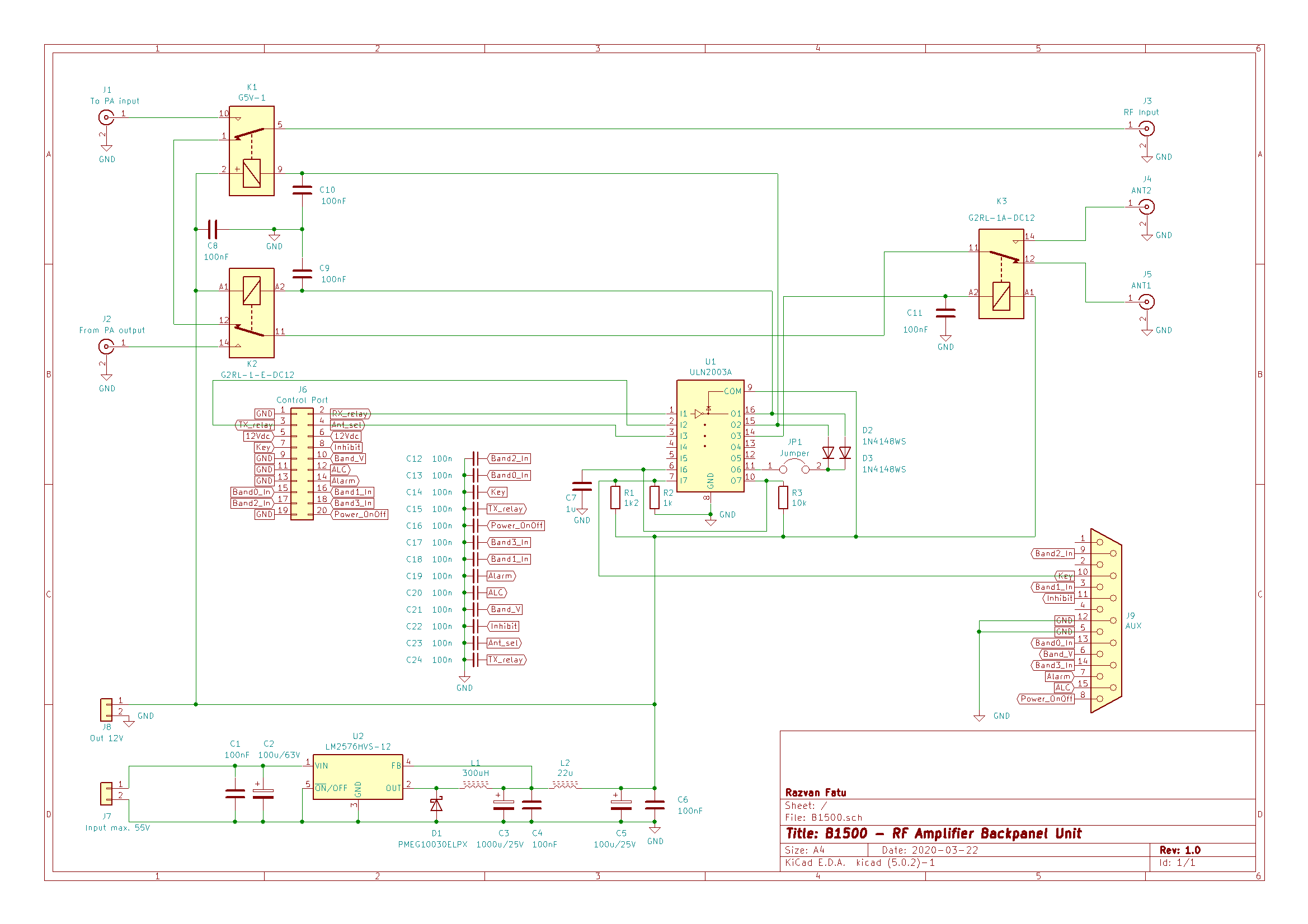
RX/TX switching is achieved with the help of two separate relays: Omron G5V-1 and Omron G2RL-1. These can safely handle up to 100W on the input side and 1500W on the output side respectively, with minor losses up to the VHF region. To allow sequencing, the two relays can be controlled separately.
Antenna switching is achieved by one Omron G2RL-1 relay; this solution is simple and reliable, isolation being very high at HF an creeping up to -35dB at 50Mhz and -25dB at 150MHz.
The onboard DC-DC converter can take an input from 15V to 55V and provides a clean output of 12V DC at a total current output of maximum 3A, with an efficiency of up to 90%. This powers the onboard circuitry and can supply other peripherals in a power amplifier such as relays, fans, control units etc. It is built around the LM2576HVT-12 regulator, using high-quality capacitors, inductors and additional output filtering. If it shares the same supply line with the Power Amplifier unit, a EMI choke is recommended at the board input.
Transceiver interfacing is done via the AUX port and uses the same standard as the Elecraft KPA1500. Pin signal description below:
| Pin | Signal Name | Direction | Notes |
|---|---|---|---|
| 1 | NC (Band Vref Icom) | In | Reference for Icom input – connect to 8V |
| 2 | NC (AuxBus I/O) | K3/K3S | |
| 3 | Band1 In | In | BCD Band Input – Bit 1* |
| 4 | NC | ||
| 5 | GND | ||
| 6 | Band V | In | Analog band data |
| 7 | Alarm Out | Out | Drives low for fault input |
| 8 | Power On/Off | In | Pulse low to turn amplifier on or off – do not hold low! |
| 9 | Band2 In | In | BCD Band Input – Bit 2* |
| 10 | Key | In | Low enables amplification. Internally pulled up to +5V |
| 11 | Inhibit# | Low inhibits amplifier operation | |
| 12 | GND | ||
| 13 | Band0 In | In | BCD Band Input – Bit 0* |
| 14 | Band3 In | In | BCD Band Input – Bit 3* |
| 15 | ALC | Out | ALC output to transceiver |
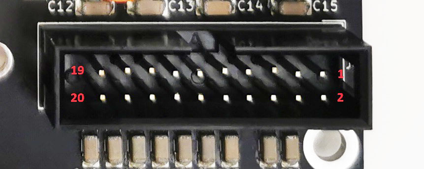
Most of the functionality should be implemented via a separate board, connected to the Control Port (20-port IDC connector):
| Pin | Name | Description |
|---|---|---|
| 1, 9, 11, 13, 19 | GND | Reference ground. |
| 2 | RX_relay (input) | Logic signal that switches the input side relay. No signal = RX mode, apply +5V to switch to TX mode. |
| 3 | TX_relay (input) | Logic signal that switches the output side relay. No signal = RX mode, apply +5V to switch to TX mode. |
| 4 | Ant_sel (input) | Logic signal that switches the antenna port. No signal = ANT1 (J5) selected, apply +5V to select ANT2 (J4). |
| 5, 6 | 12Vdc (output) | 12V supply, max 500mA combined |
| 7 | Key | PTT signal. Stays around +5V during RX, external source (transceiver) pulls this down for TX. |
| 8 | Inhibit (output) | Voltage proportional to the amplifier output reflected power square root. Around 3.20V for 600W. |
| 10 | Band_V (output) | Analog band data from transceiver. 0-8V for Icom, 0-5V for Yaesu, 0-2.5V for Xiegu; refer to transceiver specs for details. |
| 12 | ALC (input) | ALC voltage for transceiver. From 0V to -11V depending of transceiver and settings. Please note this is a negative voltage. |
| 14 | Alarm (input) | Drives low for fault input. |
| 15 | Band0_In (output) | BCD Band Input – Bit 0 (Yaesu & Elecraft standard) |
| 16 | Band1_In (output) | BCD Band Input – Bit 1 (Yaesu & Elecraft standard) |
| 17 | Band2_In (output) | BCD Band Input – Bit 2 (Yaesu & Elecraft standard) |
| 18 | Band3_In (output) | BCD Band Input – Bit 3 (Yaesu & Elecraft standard) |
| 20 | Power_OnOff (output) | Pulse low to turn amplifier on or off – do not hold low! |
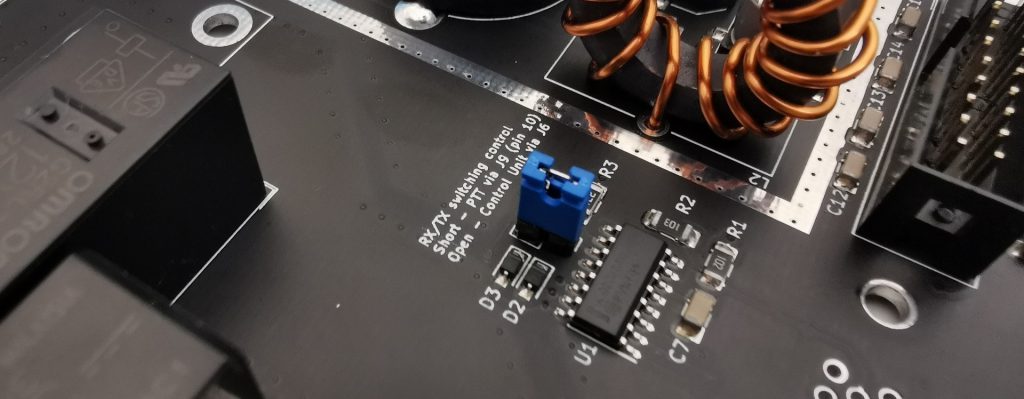
The B1500 unit can also operate in a standalone mode (without the need of anything connected to the Control Port); a jumper (JP1) must be installed in this case, to allow the board to switch from RX to TX based on the AUX Key signal. ANT 1 will be always selected and the other functionality will not work.
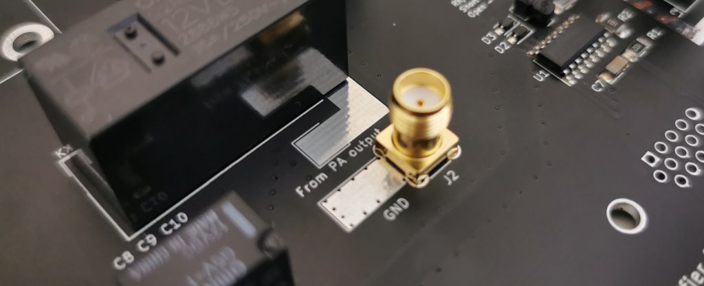
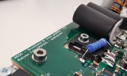
This is designed to work with amplifiers of up to 1500W, however it is recommended that above 600W the PA unit output coaxial is soldered directly to the board instead of using the SMA connector. Special pads are added for this:
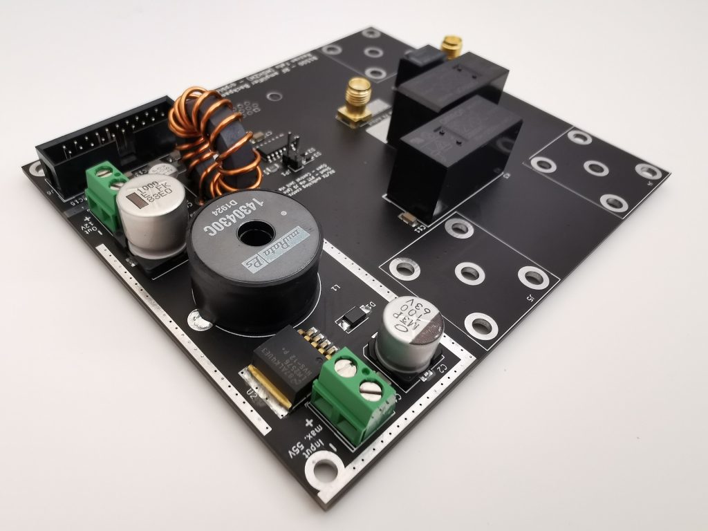
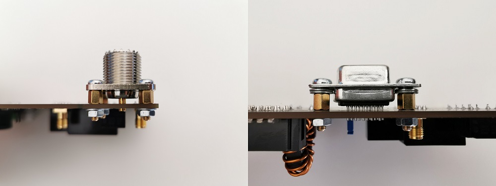
The board is designed to be mounted along the rear panel of a case, with the connectors exposed externally via adequate cut-outs.
The B1500 Backpanel Unit is available as a kit in the shop area:
B1500 RF amplifier Backpanel Unit
Additional information can be found in the Assembly Manual:
hello I am also a promoter of kicad .. I have 3 years working professionally with this software and it is wonderful. looking forward to the V6
Dear razvan,
ver ynice design of amplifier.
Do you checked how resistance the amplifier against a highrer SWR is? vy 73
Ingo